Repairing an original Vic 20
2016-12-12
early model (with the AC input)

symptoms: black screen. No video signal at all (which if there was a signal it I think would be referred to as white screen).
If you want to fix a Vic 20 or a C64 the first ref you need is Ray Carlsen's guides. http://personalpages.tds.net/~rcarlsen/cbm/vic20/vic20.txt
Also used: Vic 20 schems http://www.zimmers.net/anonftp/pub/cbm/schematics/computers/vic20/index.html
Aside from missing a CPU & one VIA (which was lifted to fix my other Vic 20) the first fault diagnosed was the bung kernel ROM 901486-07 (PAL version, with -06 being the NTSC). I found this by swapping all socketed chips, one at a time, into my working Vic 20. However, replacing this wasn't enough to progress the screen from no-signal-black.
I didn't have the proper 9v ac power supply: but that was easily solved by jumpering (ie with jumper leads, straight to the AC input socket) 12v DC from my lab power supply. For a while there I was barking up the wrong tree (not the first time in this story) - worrying about whether LM 323 was working, so I wasted some time pulling that out and testing it and putting it back in.
I started hunting around the VIC chip area. For some reason I got a bug in my ass about fixing the clock signal. Using my CRO I found that it was present: but I worried the shape of it was weird or something. In any case I ripped out UB9 and put in a socket and a fresh 74LS02. No change: still black.
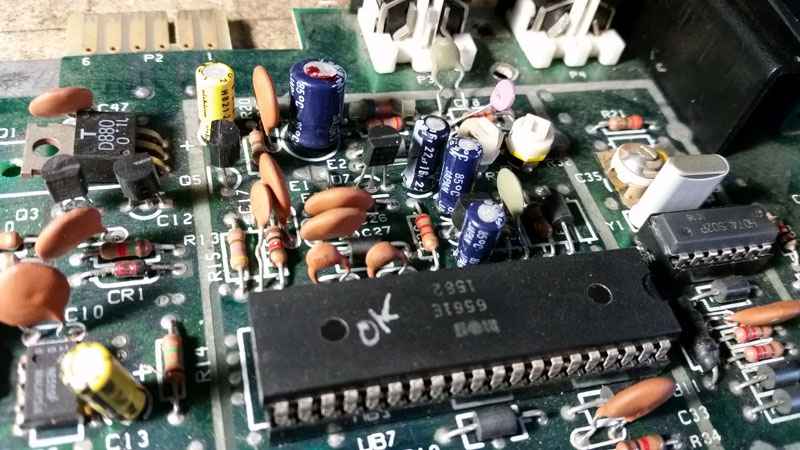
What I did next is what I should have done from the start. I took the CRO and used it to confirm that the output video signal on the video out pin of the DIN socket at the back of the Vic 20 was non existant. Then I used same CRO to see that there was indeed a signal coming from pins 2 & 3 (luma & chroma) on the VIC chip. Then it was a matter of referring to the schem and tracing the signal. Doing that, it only took about 30 sec to find that Q7 was physically destroyed! I didn't see it immediately due to the fact I was only looking at the board from one angle. Looking at it from the reverse revealed a transistor with a chunk missing. I replaced it from stock, not even checking specs: just making sure it was NPN or whatever.
Powered it up: miraculous change, but not quite cigar
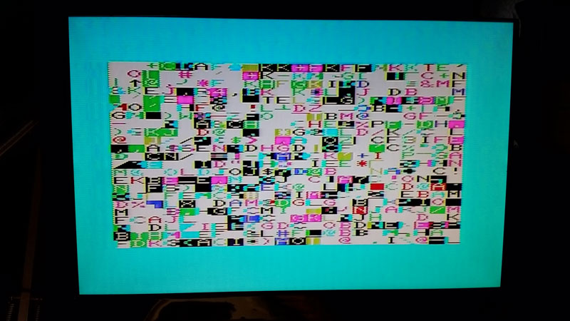
In any case I was pretty pleased to have a video signal, albeit the screen was full of garbage. Referring to Carlsen's guide, that garbage screen could be caused my any number of things: RAM, VIC or logic. I made a list and thought about it and came to the conclusion it was probably faulty RAM. I've had faulty RAM chips in 2 of my C64s so this wouldn't be surprising. The problem of course then becomes which one? There are 10 RAM chips and I didn't have a dead test cart.
I did have a spare Arduinos lying around, so I pulled out the CPU and the VIC, leaving the address and databus exposed for probing.
Arduino in-circuit RAM tester
RAM is theoretically easy to test: set the address, set the data, set R/W to low (to write) and set CS (chip select) low. Then set R/W high and read the data while keeping the address the same. Data read should match data written. Best to test as many data/address combinations possible. 2114 have 10 address bits and 4 data bits. So you can use the Arduino to cycle through 1024 addresses and 16 datas. Test one RAM chip at a time by maniuplating the CS logic on the main board (this was the trickiest bit) around UC4.
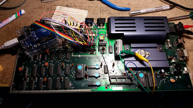
The RAM tester was connected with breadboard-leads directly from the Arduino to the VIC chip.
Having determined UE4 was fried and then waiting 3 weeks or so for the new-old 2114 RAM to arrive from China, I whacked in a socket and the new 2114 - bingo: fixed! a boot up screen .... but wait:
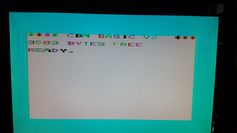
Final problem: characters have wrong colors. Well this was easy, because according to Ray this is the UD1 4066. I had some of these socketed in a project so I ripped the old one out, put in a socket and a borrowed 4066 of mine.
Vic 20 fixed!
So it went from a complete piece of shit to a working Vic 20. Total list of replaced parts:
- CPU
- kernal rom
- transistor in video circuit (Q7)
- 7402 (not broken but replaced anyway)
- 1x ram chip
- 4066 color logic
It's still missing 1 VIA (for the disk IO etc) and a kernal ROM which will be the hardest thing for me will be to source. But a fun & satisfying fix, especially signal tracing with a CRO and building an in-circuit RAM tester.
See also: repairing four c64s